Step 1: Connect The TX Repeater Cable To The RJ45 Terminal Block
One of the repeater cables will be a designated "TX" and one will be a designated "RX" cable. Strip the outer jacket back to expose the inner cable strands. There will be the following 5 exposed wires on each cable. Once the wires are exposed, strip about a half of an inch (13mm) off each colored cable while being careful not to cut the cable itself.
Color
Pin
Purpose
White
5
Flat Tx Audio
Black
3
PTT
Green
11
Rcv Audio
Red
8
Cos
Bare
7
Ground
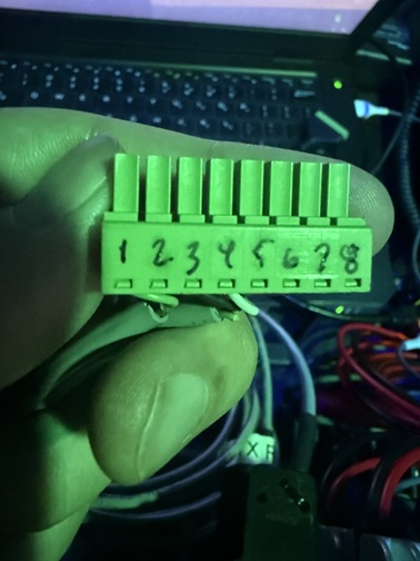
Holding the terminal block with the screw side facing down, take a sharpie and number from left to right, 1 through 8 over each of the gates.
Reference Photo
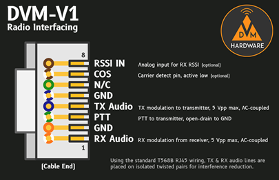
Using the diagram from the DVMProject GitHub for the DVM-V1 Duplex Modem below, connect the following wires to the appropriate gate.
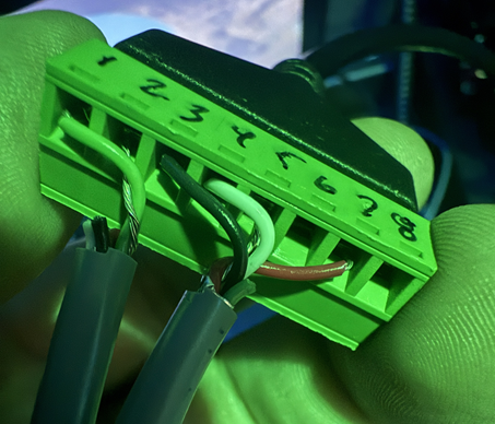
Once wired, the cable should look something like this when finished. I snipped the unused cables off of the RX cable so that only "Green" and "Bare" were remaining to help discern which cable was which at a glance and reduce mistakes wiring.
Reference Photo
Each of the 20-pin adapters should then be plugged into their respective radio (TX to TX, RX to RX) and the ethernet side should be plugged into the DVM-V1 Duplex Modem.